Digital Video Broadcasting: DVB-S2, DVB-T2, DVB-C Guide
Introduction
Live sports, satellite news feeds, and even basic cable channels all rely on the same quiet engine in the background, called digital video broadcasting. Viewers just see a channel list and a picture on screen. Engineers see modulation schemes, code rates, symbol rates, and link budgets. The gap between those two views is exactly where standards like DVB-S2, DVB-T2, and DVB-C sit.
Digital Video Broadcasting, or DVB, gives broadcasters a common rulebook for sending audio, video, and data over satellite, terrestrial, and cable networks. These broadcast standards make it possible for receivers from different vendors to talk to networks built by different operators while still delivering reliable services to more than a billion devices. For anyone who works with contribution feeds, DTH platforms, or hybrid OTT and broadcast workflows, understanding how DVB fits together is not just nice to have, it is part of daily design and troubleshooting.
This article walks through the core ideas behind digital video broadcasting, then dives into DVB-S2 for satellite, DVB-T2 for terrestrial, and DVB-C and DVB-C2 for cable. It explains how each one handles its transmission environment, what gains the second generation brings, and how codecs, metadata, and security complete the system. Along the way, it points out practical engineering trade-offs and where resources like TVTechInsight help with deeper design choices, from compression to multiplexing. By the end, the big DVB picture should feel clear enough to support real decisions on networks and workflows.
What Is Digital Video Broadcasting (DVB)?
Digital Video Broadcasting is a family of open broadcast standards that define how digital television signals move from headend to receiver. The DVB Project, a large industry group with broadcasters, manufacturers, and network operators, develops the specifications. These documents are then published by a joint committee that includes ETSI, CENELEC, and the EBU, which gives DVB the formal status engineers expect for long term infrastructure.
“Standards are the hidden glue of broadcasting — when they work, nobody notices; when they fail, everybody does.”
— Common saying in broadcast engineering teams
At its core, digital video broadcasting replaces analog RF with digital symbols. This change lets engineers pack far more services into the same slice of spectrum while raising audio and video quality. Moving to DVB also freed large parts of the UHF band, sometimes called the digital dividend, which regulators reallocated to mobile networks and other services. Because DVB is an open standard, set top boxes, integrated TVs, IRDs, modulators, and multiplexers from different vendors can interoperate as long as they follow the same profile.
DVB is flexible by design. It carries video compressed with MPEG-2, H.264/AVC or HEVC, and it supports several audio formats, from MP2 and AC-3 to AAC and beyond. Underneath, all mainstream DVB systems use MPEG Transport Stream (MPEG-TS) as the container. Different physical-layer flavors then sit under the same TS structure. DVB-S2 targets satellite, DVB-T2 targets terrestrial broadcasting, and DVB-C targets cable. Around the world, DVB competes with ATSC in North America, ISDB in Japan and much of South America, and DTMB in China, but DVB remains the dominant choice across Europe, Africa, Australia, and large parts of Asia.
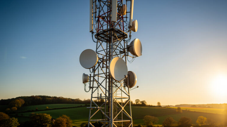
DVB-S2 Satellite Broadcasting Standard
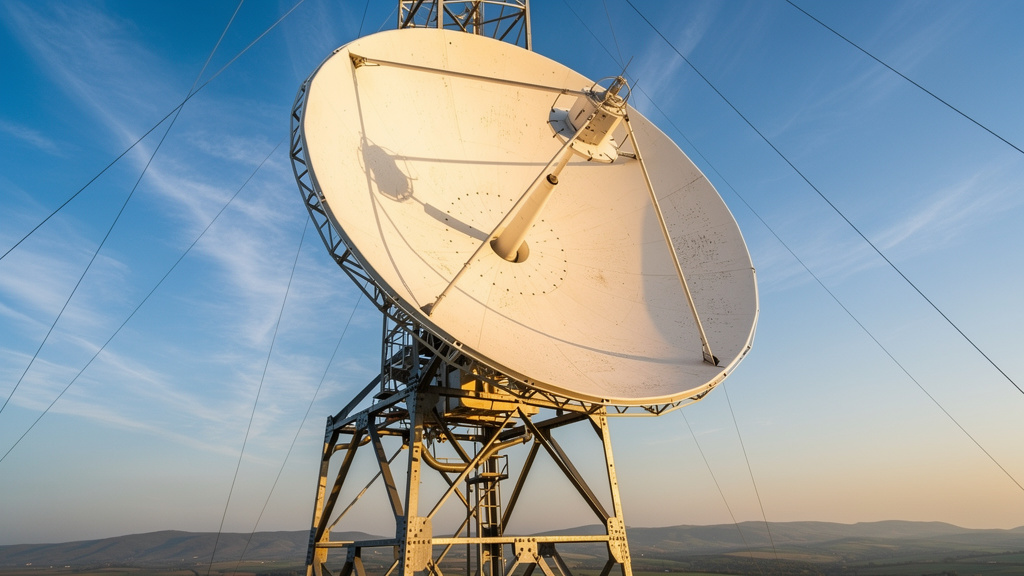
DVB-S2 is the second generation satellite standard in the digital video broadcasting family, replacing the original DVB-S that dates back to the mid 1990s. It keeps the same basic role, sending multiplexed transport streams over satellite links, but it raises capacity by roughly thirty percent compared with DVB-S under similar conditions. That extra throughput comes from better modulation and much stronger forward error correction rather than from more spectrum.
A DVB-S2 carrier can use QPSK, 8-PSK, 16-APSK, or 32-APSK. Higher order constellations carry more bits per symbol but need a cleaner signal and better signal to noise ratio. Forward error correction uses a combination of LDPC and BCH codes. LDPC handles most of the corrections, while BCH cleans up the remaining errors so the overall bit error rate after FEC can be extremely low, which is vital for stable DTH platforms and contribution links.
One important feature of DVB-S2 is support for Variable Coding and Modulation (VCM) and Adaptive Coding and Modulation (ACM). VCM lets an operator send different services in the same multiplex with different code rates and constellations, so for example a key HD channel can run with higher protection than a secondary channel. ACM goes a step further and adjusts parameters per receiver or per beam based on link conditions, which is very useful for professional links or broadband over satellite. DVB-S2X extends this standard with higher order APSK levels up to 256-APSK, smaller roll off factors for tighter packing of carriers, and better support for channel bonding and advanced IP transport through mechanisms such as Generic Stream Encapsulation (GSE). DVB-S2 and DVB-S2X operate across C band, Ku band, and Ka band, so engineers balance rain fade, antenna size, and available spectrum when they design their links.
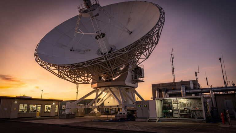
DVB-S2 Implementation Workflow
A practical DVB-S2 chain starts with contribution or playout sources that feed encoders. Video is compressed with H.264 or HEVC, and audio uses formats such as AAC or AC-3, with bitrates chosen to match the target service quality and total transponder capacity. All compressed streams enter a multiplexer that builds an MPEG Transport Stream and inserts DVB Service Information (DVB-SI) so receivers can tune services and build a program guide.
That transport stream moves to the DVB-S2 modulator. Here the operator selects the modulation scheme, FEC code rate, roll off factor, and symbol rate that match the desired capacity and link margin. Uplink equipment then converts the IF signal to the chosen satellite band, sets polarization, and sends it through a high power amplifier to the antenna pointing at the satellite orbital slot.
On the receive side, customers or downlink sites use dishes sized for the link budget, with LNBs set to the right band and polarization. Receivers demodulate the DVB-S2 waveform, apply LDPC and BCH correction, recover the transport stream, and then decode audio and video.
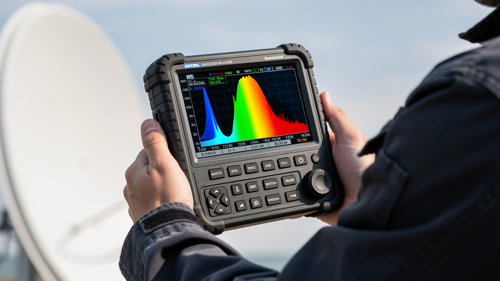
To keep services stable, monitoring systems track:
-
MER (Modulation Error Ratio)
-
BER before and after FEC
-
Link margin to rain fade and other impairments
This feedback loop lets engineers adjust parameters or maintenance plans before viewers notice problems.
DVB-T2 Terrestrial Broadcasting Standard
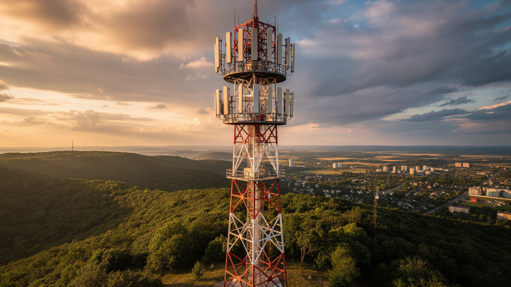
DVB-T2 is the second generation terrestrial standard for digital video broadcasting. It replaces DVB-T in many markets and makes far better use of limited terrestrial spectrum. In comparable setups, DVB-T2 can carry more than fifty percent more data than DVB-T, which allows networks to move from SD to HD and even to UHD services within the same channel plan.
The physical layer of DVB-T2 is based on COFDM. The transport stream is split across thousands of low rate subcarriers, which makes the signal very resistant to multipath, echoes, and frequency selective fading. Modulation can be QPSK, 16-QAM, 64-QAM, or 256-QAM. As with DVB-S2, LDPC and BCH handle error correction, delivering strong protection even in harsh over the air conditions. Time and frequency interleaving spread errors so the FEC has a better chance to correct them.
DVB-T2 offers many tuning knobs for network design. Engineers can choose FFT sizes from 1K up to 32K, which helps balance Doppler tolerance and SFN performance. Guard interval options range from 1/128 up to 1/4, so large Single Frequency Networks (SFNs) with wide spacing between transmitters can still work, although long guard intervals reduce useful bitrate. A key addition is the idea of Physical Layer Pipes (PLPs). PLPs let one RF multiplex carry services with different robustness levels, for example a very robust PLP for mobile or indoor reception and a higher rate PLP for rooftop antennas. There is also a T2 Lite profile that cuts overhead and increases protection for handheld or portable reception.
DVB-T2 Network Planning Considerations
Designing a DVB-T2 network starts with spectrum plans and channel bandwidth. Some regions use 8 MHz channels, others use 7 or 6 MHz, and the capacity model changes with that input. Engineers then choose transmitter sites and antenna heights so they can cover target areas with enough field strength, while also taking terrain and clutter into account through coverage prediction tools.
“Do the coverage study before you climb the tower.”
— Field advice from terrestrial network planners
Single Frequency Networks are a major strength of DVB-T2, but they need very accurate timing. Transmitters in an SFN lock to GPS or another stable reference so they radiate the same waveform at nearly the same time. Antenna patterns and power levels are shaped to control overlaps and limit self interference. During rollouts, field measurements of MER, carrier to noise ratio, and delay spread guide fine tuning.
When upgrading from DVB-T, operators often run a simulcast phase and gradually replace receivers. They usually reuse existing tower sites but update modulation and error correction to the DVB-T2 configuration that best matches their service mix and energy targets. Careful parameter selection often allows more HD channels or extra multiplexes without needing extra spectrum.
DVB-C And DVB-C2 Cable Broadcasting Standards
DVB-C covers digital video broadcasting over cable networks that use coaxial cable and sometimes optical links in the backbone. Because the cable plant is shielded and has lower external noise than air or satellite paths, DVB-C can use higher order QAM with fewer concerns about fading or multipath. Common constellations include 16-QAM, 64-QAM, 128-QAM, and 256-QAM, and higher levels give more bits per symbol at the cost of more sensitivity to noise inside the plant.
The DVB-C physical layer is relatively simple compared with DVB-T2 or DVB-S2. It uses single carrier QAM on each RF channel, with Reed Solomon coding and convolutional interleaving for error protection in many deployments. This is well suited to legacy receivers and still serves many cable systems worldwide. As demands for more HD and UHD capacity grow, however, DVB-C2 becomes more attractive because it brings OFDM, LDPC and BCH error correction, and QAM constellations all the way up to 4096-QAM for very clean networks.
DVB-C2 can deliver more than thirty percent extra capacity within the same channel spacing compared with DVB-C. It also supports time and frequency interleaving, which raises tolerance to impulse noise from sources such as home appliances. Channel bonding groups multiple RF channels to act as a larger pipe, useful for very high bitrate services or shared capacity with DOCSIS based data. Transport into both DVB-C and DVB-C2 can be classic MPEG Transport Stream or Generic Stream Encapsulation for more efficient IP carriage, which matters as cable operators mix broadcast, IPTV style services, and broadband over the same physical plant.
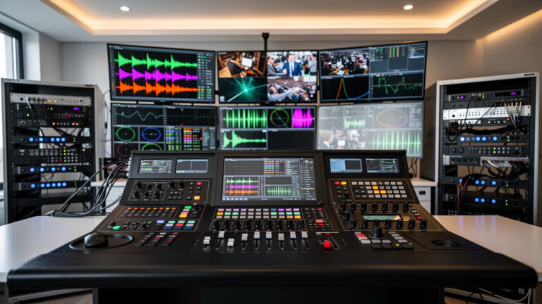
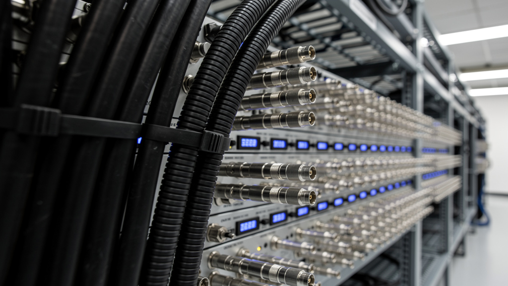
DVB-C/C2 Deployment Architecture
A DVB-C or DVB-C2 deployment starts at the cable headend. Encoders compress video and audio, and then multiplexers assemble transport streams from those compressed services. Statistical multiplexing is common here, so channels share bitrate based on moment to moment complexity instead of having fixed allocations. The outputs feed QAM modulators or DVB-C2 modulators, which upconvert to the required RF channels.
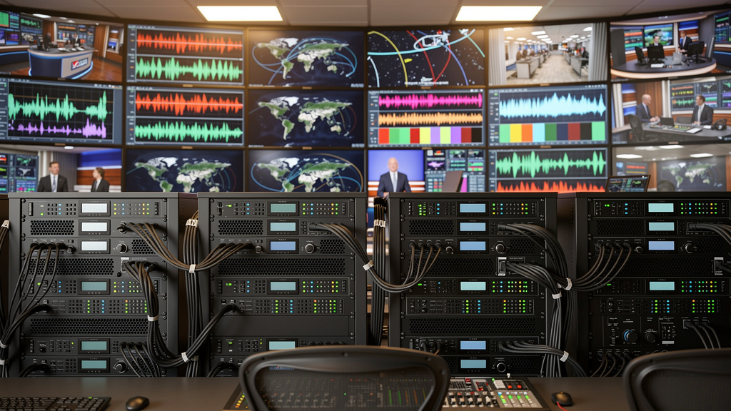
Those RF carriers are combined and sent through amplifiers and optical transmitters that feed the HFC network. Downstream, optical nodes convert the signal back to RF, and cascades of amplifiers drive it along coaxial branches all the way to the subscriber outlet. Set top boxes and integrated cable tuners then demodulate DVB-C or DVB-C2, feed transport streams to decoders, and display services. Monitoring systems inside the headend and in the field track carrier levels, modulation error ratio, and error rates so maintenance teams can keep quality within tight limits while the plant scales to more services.
Comparing DVB-S2, DVB-T2, And DVB-C Technical Specifications
DVB-S2, DVB-T2, and DVB-C address very different physical paths, so their technical designs match those conditions. Satellite links in DVB-S2 follow a clear, line of sight path with long distance and no multipath, so they use single carrier PSK and APSK modulation without guard intervals. Terrestrial DVB-T2 works in a harsh over the air channel with echoes, mobile receivers, and variable terrain, so it uses OFDM with many subcarriers, long guard intervals, and both time and frequency interleaving. Cable based DVB-C sits in a shielded and controlled environment, so it can use dense QAM without the overhead of long guards or heavy interleaving.
All three families use strong forward error correction, but the second generation standards share one scheme. DVB-S2, DVB-T2, and DVB-C2 all rely on LDPC combined with BCH, with several code rates available. Lower code rates such as one half give better protection but lower payload, while higher rates like five sixths carry more user bits but require better link conditions. First generation DVB-C usually uses Reed Solomon codes and interleaving instead of LDPC, which still works well for many plants but is less capacity efficient.
Interleaving strategies also differ:
-
DVB-S2 uses bit interleaving and pilots inserted in a pattern suited to satellite channel estimation.
-
DVB-T2 and DVB-C2 both use spreading across time and frequency, which helps against impulsive and frequency selective noise.
At the input side, all standards can accept multiple transport streams or generic streams, which gives operators flexibility to carry both classic broadcast channels and IP based services. When engineers compare these systems for a new platform, they weigh spectral efficiency, typical SNR in the field, receiver cost, and infrastructure already in place. DVB-S2 and DVB-T2 need more complex demodulators and often higher grade RF front ends, while DVB-C receivers are simpler but depend on a well maintained cable network.
Video And Audio Codecs In DVB Systems
DVB standards focus on how bits move over RF or cable, not on how those bits get compressed, yet codec choices define how many services fit into a multiplex and how they look and sound. That is why digital video broadcasting deployments always treat codec planning as a key design layer. Early DVB networks used MPEG-2 video for SD, which is easy to decode but needs relatively high bitrates. As HD became common, H.264/AVC took over because it delivers similar or better quality at much lower bitrates.
For UHD and higher frame rate content, HEVC/H.265 is now common in DVB based systems. It uses more advanced prediction and transforms, still building on ideas such as the Discrete Cosine Transform but in a more flexible structure. Newer codecs like VVC/H.266 and AV1 promise further bitrate savings, which will help when 8K or very high frame rate services spread, but decoder support in consumer devices is still moving forward and must be checked before any large scale rollout.
On the audio side, DVB streams often carry MP2, AC-3, or E-AC-3, with AAC and HE-AAC used in many DVB-T2 networks, especially where bandwidth is tight. Next generation audio formats such as MPEG-H 3D Audio and Dolby AC-4 add objects and height channels, which support immersive and personalized mixes.
A simple way to think about codec planning is:
-
Use MPEG-2 only where legacy receivers force it.
-
Use H.264 for HD where devices or STBs do not support HEVC.
-
Use HEVC for 4K, HDR, or very bandwidth sensitive setups.
-
Trial VVC or AV1 carefully where compatible receivers exist.
Bitrate management across video and audio usually mixes fixed target rates and statistical multiplexing, so the full multiplex stays within the capacity of DVB-S2, DVB-T2, or DVB-C while still reacting to content complexity. TVTechInsight spends a lot of time on these codec and rate control details, since they are central to efficient end to end digital video broadcasting workflows.
DVB Service Information And Metadata (DVB-SI)
A pure transport stream with only audio and video packets would be hard for receivers to use. DVB-SI fills that gap by adding structured metadata that describes services, events, and networks. The main specification is ETSI EN 300 468, and it defines a set of tables that receivers read continuously to know what is on each frequency and inside each multiplex.
Some tables come from the underlying MPEG-2 Program Specific Information, such as the Program Association Table (PAT) and Program Map Table (PMT), which link program numbers to PIDs. DVB-SI adds:
-
Network Information Table (NIT) – describes the wider network and how to find other multiplexes.
-
Service Description Table (SDT) – provides human readable service names and flags for properties such as free to air or scrambled.
-
Event Information Table (EIT) – describes current and upcoming shows with start and end times, titles, and short text, which becomes the familiar Electronic Program Guide.
“Treat SI as your control plane. If viewers cannot browse, they assume the whole service is broken.”
— Operations teams in broadcast headends
DVB-SI uses a Modified Julian Day based time format, and the choice of field width leads to a known overflow in 2038 that standard bodies and implementers need to handle. For richer metadata and better support for personal video recorders, DVB also adopted TV Anytime concepts under the DVB-TVA label, which use XML schemas for much more detailed descriptions. Engineers have to watch SI bitrate overhead and repetition rates, since sending tables too often wastes capacity while slow repetition makes channel changes and EPG updates feel sluggish to users.
Conditional Access And Security In DVB Broadcasting
Most subscription television over DVB uses some form of Conditional Access (CA) so only paying customers can watch protected content. The DVB-CA framework defines how this control fits into the digital video broadcasting system, while leaving space for many different commercial CA systems to compete. At the heart of the chain, DVB-CSA scrambles video and audio packets with a common algorithm, so hardware and software implementations can be shared across platforms.
Access control then comes from smart cards, keys, and entitlement messages managed by the CA provider. The DVB Common Interface (CI) defines a slot in the receiver and a protocol for Conditional Access Modules (CAMs). A CAM understands one CA system and works with a matching smart card or embedded key set. Receivers can support several CA systems by accepting different CAMs, which gives operators and customers more freedom. CI Plus strengthens the link between host receiver and CAM by adding authentication and encryption on that internal path, which makes attacks that tap that interface harder.
Beyond classic smart card security, DVB specifications also addressed how content is handled after descrambling. DVB-CPCM tried to set rules for copy management and home network redistribution, but after years of debate and low market interest, it was deprecated in 2019. In practice, modern DVB based platforms rely on a mix of:
-
CA systems and entitlement management
-
Secure chipsets in set top boxes or TVs
-
Firmware that resists tampering
-
Strict control of key distribution and update channels
These measures add some overhead and code complexity, but they are essential for pay TV business models and for protecting high value events carried over DVB-S2, DVB-T2, or DVB-C.
DVB-I Bridging Broadcast And Internet Delivery
As more viewing shifts to IP based services, the DVB Project introduced DVB-I to link classic digital video broadcasting with internet delivery. DVB-I does not replace DVB-S2, DVB-T2, or DVB-C at the RF layer. Instead, it focuses on discovery and metadata so that a TV or app can present broadcast and OTT channels in one consistent list. The aim is simple. From the viewer point of view, a channel is a channel, whether it reaches the screen over satellite, terrestrial RF, cable, or pure IP.
DVB-I, standardized as ETSI TS 103 770, defines Service List Registries (SLRs) and a way for clients to find and fetch those lists over the internet. A service list can include entries for plain RF services, pure IP streams, or both, with enough metadata for the client to pick the best path that device can handle. If a broadcast signal is weak or missing, a receiver can fall back to an internet version of the same channel if the operator offers one, without the user needing to care about the switch.
DVB-I builds on earlier DVB-IPTV work such as DVB-IPI and the Broadband Content Guide, but it targets the open internet more directly and does not assume a fully managed network. Trials in countries such as Germany, Italy, Spain, Ireland, and Iran show how DVB-I can let broadcasters keep linear channels while feeding OTT platforms and apps from a shared discovery layer. For engineers, DVB-I adds another dimension to digital video broadcasting design, since it ties broadcast headends, CDN workflows, and client apps together through common metadata and behavior.
Conclusion
DVB-S2, DVB-T2, and DVB-C sit at the heart of modern digital video broadcasting, each tuned to a different medium. DVB-S2 and its DVB-S2X extension push satellite capacity with LDPC and BCH codes, APSK constellations, and modes such as ACM and VCM for fine control of performance. DVB-T2 uses COFDM, long guard intervals, PLPs, and SFNs to squeeze more bits into scarce terrestrial spectrum while still coping with reflections and mobile reception. DVB-C and DVB-C2 turn the cleaner cable plant into high capacity QAM based pipes that pair well with DOCSIS and IPTV style services.
Across all three, second generation standards use similar FEC ideas and share MPEG Transport Streams and DVB-SI metadata, which gives engineers a common mental model even as they move between satellite, terrestrial, and cable projects. The future of digital video broadcasting will lean on these foundations while adding DVB-I for hybrid broadcast and IP service discovery, new codecs such as VVC and AV1 for higher resolution, and immersive audio formats for richer sound fields.
Keeping up with these shifts takes time and careful reading of standards. TVTechInsight focuses on this full chain, from encoding and multiplexing through DVB physical layers to security and receiver behavior. For teams that design, operate, or migrate DVB based platforms, TVTechInsight offers deep technical articles that go beyond surface summaries. The next step is to use these insights in real designs, then return to TVTechInsight whenever a new detail in digital video broadcasting needs a clear and practical explanation.
FAQs
Question: What Is The Primary Difference Between DVB-S2 And DVB-T2?
DVB-S2 targets satellite links, so it uses single carrier modulation with constellations such as QPSK, 8-PSK, and APSK, and it does not need guard intervals because the channel has almost no multipath. It is designed for long distance point to multipoint delivery from a satellite footprint to many dishes. DVB-T2, in contrast, uses OFDM with many subcarriers and several guard interval options to fight echoes and reflections in over the air terrestrial paths. Both share LDPC and BCH error correction, but their physical layers match very different propagation environments.
Question: Can I Use The Same Receiver For DVB-S2, DVB-T2, And DVB-C?
A single device can support DVB-S2, DVB-T2, and DVB-C, but it needs separate tuners and demodulators for satellite, terrestrial, and cable RF inputs. Many consumer receivers focus on one or two of these, while professional IRDs often include multi standard front ends. Satellite inputs usually use F type connectors and handle L band from an LNB, terrestrial inputs often use IEC antenna connectors, and cable tuners expect the levels and channel plans of the HFC network. Inside the box, though, all three paths can share the same transport stream demultiplexer and decoder blocks, since DVB uses MPEG-TS across standards.
Question: What Forward Error Correction Do Second-Generation DVB Standards Use?
Second generation DVB standards, which include DVB-S2, DVB-T2, and DVB-C2, all rely on a concatenated FEC approach with LDPC and BCH. LDPC codes provide powerful near Shannon limit performance for random errors, while BCH acts as an outer code that corrects any remaining errors that slip through. Each standard offers several code rates so operators can choose the balance between protection and net bitrate that fits their link margin and service goals. This shared FEC design is a big part of the gain in capacity compared with earlier DVB generations.
Question: How Do I Choose Between DVB-C And DVB-C2 For A New Cable Network?
Choosing between DVB-C and DVB-C2 starts with an honest view of cable plant quality and service plans. DVB-C, with 64-QAM or 256-QAM, is mature and has very wide device support, which makes it a safe pick when many legacy receivers are in the field and HD services are the main need. DVB-C2 adds OFDM, LDPC and BCH, and very high order QAM up to 4096-QAM for clean networks, which raises capacity by more than thirty percent. For greenfield builds that aim at many HD and UHD channels plus shared IP services, DVB-C2 gives more room, while mixed networks may run both modes during a migration period.
Question: What Video Codec Should I Use With DVB-T2 For 4K UHD Broadcasting?
For 4K UHD over DVB-T2, HEVC/H.265 is the practical choice because it cuts the bitrate roughly in half compared with H.264 for similar visual quality. Many real world deployments use between fifteen and twenty five megabits per second for a 4K HEVC service, depending on frame rate, content type, and quality targets. Receivers must support HEVC Main 10 for HDR content, so device capability checks are important before launch. Over time, VVC or H.266 may take over once decoders are common, but for current DVB-T2 networks, HEVC remains the main option. TVTechInsight covers these codec choices in depth for engineers planning new UHD multiplexes in digital video broadcasting systems.