DVB-T2 and OFDM: Modern Terrestrial Digital TV Guide
Introduction
When someone connects a small indoor antenna to a modern TV and sees crisp HD channels, it feels almost effortless. Behind that simple act sits a dense stack of radio, compression, and network engineering. For much of the planet that stack centers on DVB-T2, the second-generation standard for terrestrial digital TV. It takes familiar OFDM broadcasting and pushes it far beyond what first-generation systems delivered. For many engineers it is the reference point for modern terrestrial networks.
Analog terrestrial television wasted spectrum and left room for only a few channels. DVB-T changed that by digitizing the signal, yet its capacity and flexibility began to hit limits once HD, UHD, and mobile reception entered the picture. DVB-T2 arrived as a deep technical upgrade that squeezes around thirty to seventy percent more useful data into the same RF channel. It does this while reusing existing transmitter networks and rooftop antennas, which made nationwide rollouts realistic for regulators and broadcasters.
Broadcasters across Europe, Asia, Africa, and other regions now rely on DVB-T2 to carry large bouquets of HD and even UHD services. For video engineers, encoding specialists, OTT platform teams, and broadcast planners, the standard ties codec choices, multiplex design, and physical layer parameters together very tightly. Understanding those ties is often the difference between fitting one UHD service in a multiplex or two. In this article we at TVTechInsight walk through DVB-T2’s architecture, signal structure, modulation, Physical Layer Pipes, T2-Gateway and T2-MI, and the T2-Lite profile so that the whole chain from encoder to antenna becomes easier to reason about.
As the DVB Project notes in its overview, DVB-T2 was designed to provide at least 30% higher data rate than DVB-T under similar reception conditions.
Key Takeaways
Before we go deep into parameters and frame diagrams, it helps to see the big picture. The points below sum up what DVB-T2 brings to terrestrial networks. Keeping them in mind makes the later details easier to connect.
Higher Capacity: DVB-T2 can deliver roughly forty six to sixty seven percent more capacity than DVB-T in real networks. It reaches this by combining LDPC and BCH error protection, higher-order QAM, and long OFDM symbols. That extra capacity turns directly into more HD or UHD services in the same RF channel.
Service-Specific Protection: Physical Layer Pipes (PLPs) let each service run with its own protection and bit rate inside one multiplex. A single channel can mix QPSK for mobile, sixteen or sixty four QAM for general HD, and two hundred fifty six QAM for rooftop UHD. Receivers can focus only on the PLP they need, which also saves power.
Deterministic SFNs: A central T2-Gateway plus the T2-MI interface keep Single Frequency Networks (SFNs) deterministic. They tell every modulator exactly what to send, where to place each PLP, and when to transmit each frame. That model supports clean SFN operation and even regional content insertion.
Mobile-Friendly Profile: The T2-Lite profile trims the mode set and adds very strong code rates so that mobile and handheld receivers stay simple and low power. It can share a frequency with normal T2 Base services using Future Extension Frames. This lets one network reach living-room TVs and phones at the same time.
End-To-End Impact: Understanding DVB-T2 in isolation is not enough for modern operations. Real results depend on how encoding, statistical multiplexing, PLP layout, and RF planning work together, which is exactly the full video lifecycle we focus on at TVTechInsight.
What Is DVB-T2 And Why It Matters For Modern Broadcasting

DVB-T2 stands for Digital Video Broadcasting – Second Generation Terrestrial and it is specified by ETSI (EN 302 755). It is the follow-up to DVB-T for terrestrial TV services that use OFDM broadcasting. The design goal was clear from the start: reach at least thirty percent more throughput than DVB-T under the same planning rules. At the same time the standard had to fit into existing transmitter infrastructure and domestic antennas so that migration stayed affordable.
To reach that goal the standard set a number of commercial and technical requirements, including:
Strong performance in Single Frequency Networks (SFNs), where several transmitters reuse the same RF channel over large areas.
The ability to give some services very strong protection and others higher bit rate within one multiplex, instead of forcing a single compromise setting.
Flexible bandwidth options so that countries with six, seven, eight, or ten megahertz channels can all adopt the same family of tools.
Those ideas turned into a system that is now the main terrestrial platform across Europe, much of Asia, large parts of Africa, and beyond. Operators use DVB-T2 for nationwide free-to-air HD lineups, for terrestrial pay TV, and for mobile or handheld services through the T2-Lite profile. Compared with DVB-T, the extra capacity often means an entire multiplex of additional HD channels with no extra spectrum. Even in regions where ATSC or ISDB-T dominate, many device makers and chip vendors still study DVB-T2 as a reference for how far a terrestrial system can be pushed.
“Spectrum is expensive. Standards like DVB-T2 are about squeezing every last bit per hertz without breaking receiver complexity.” – Broadcast systems engineer, EBU workshop
Core Technical Architecture – How DVB-T2 Systems Are Structured

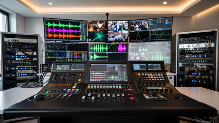
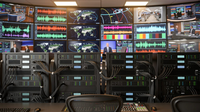
In practice a DVB-T2 network looks less like a single box and more like a chain of well-defined subsystems. The reference model divides the chain into three blocks on the network side and two on the receiver side. This split helps engineers see where compression ends, where scheduling lives, and where pure RF work begins. It is also the key that lets large SFNs run in a stable way.
The five subsystems are:
Subsystem 1 (SS1) – Coding And Multiplexing
Encoders produce compressed video and audio streams using codecs such as AVC or HEVC. A multiplexer combines them into one or more MPEG transport streams or generic streams. This is where bit rate control, statistical multiplexing, and service-level priorities are applied.Subsystem 2 – T2-Gateway
The T2-Gateway is the central brain of a DVB-T2 network. It adapts incoming streams into PLPs, schedules them in time and frequency, assigns capacity, and writes everything into a precise T2-MI stream that downstream modulators can follow.Subsystem 3 – DVB-T2 Modulator
Located at each transmitter site, the modulator reads the T2-MI stream, applies LDPC and BCH error protection, interleaving, constellation mapping, and OFDM processing, then feeds the power amplifiers that drive the antenna.Subsystem 4 – Receiver Demodulator
On the receiver side, this block tunes the RF channel, performs synchronization, and reverses the FEC and interleaving steps to rebuild transport or generic streams.Subsystem 5 – Stream Decoder
This familiar block splits out individual programs, runs video and audio decompression, handles metadata and subtitles, and presents pictures and sound to the viewer.
The reason this architecture puts so much intelligence into the T2-Gateway is simple: every transmitter in an SFN must put out the same waveform at the same instant. If each modulator tried to make its own scheduling choices, overlap regions would fall apart. By centralizing those decisions, operators can add or move transmitters without touching encoders or multiplexers. At TVTechInsight we spend a lot of time on that upstream part of the chain, because choices at the encoder and multiplexer shape what the T2-Gateway can safely schedule into each PLP.
The DVB-T2 Signal Structure – Frames, Preambles, And Logical Organization
Physical Frame Hierarchy
On the air, a DVB-T2 signal is not just a flat stream of OFDM symbols. It follows a clear hierarchy that starts with the superframe, a container that can hold up to two hundred fifty five T2 frames and optional Future Extension Frame (FEF) parts. This repeating pattern defines how base DVB-T2 and additions such as T2-Lite share time on the same RF channel. All of the high-level timing and extension information appears in Layer 1 (L1) signaling so that receivers can follow along. FEFs act as reserved time slots that older receivers can safely skip while newer systems carry extra waveforms there.
Inside the superframe, each T2 frame is the main workhorse for payload data:
A frame begins with a very strong P1 preamble symbol that lets a receiver detect the signal quickly, measure the basic mode such as FFT size and SISO or MISO use, and lock even when the tuner has a large frequency error of several hundred kilohertz.
One or more P2 symbols follow and carry the main Layer 1 fields, split into an L1-pre part with static parameters and an L1-post part that holds dynamic information about PLPs and their placement.
After that come hundreds of data symbols and sometimes a frame closing symbol with denser pilots that help with channel tracking near the end of the frame.
The total T2 frame duration can reach up to about a quarter of a second depending on configuration.
Logical Data Organization
Parallel to this physical frame layout sits a logical structure that follows each Physical Layer Pipe (PLP) from input bits to OFDM cells. The T2-Gateway first chops the incoming stream for a PLP into Baseband Frames (BBFRAMEs), each with a small header that carries synchronization and format flags. These BBFRAMEs feed the BCH and LDPC error protection chain, which turns each one into a fixed-size FECFRAME codeword of either sixteen thousand two hundred or sixty four thousand eight hundred bits. Because the length is fixed, the protection and interleaving blocks downstream can follow a very regular pattern.
After channel coding:
Bits are interleaved and mapped to constellation points, forming what the standard calls an FEC block, still in one-to-one relation with the original BBFRAME.
These blocks are then spread in time and frequency by interleaving to build an Interleaving Frame, which can cover part of a T2 frame or span several frames in a row.
Errors from noise or interference get scattered before they reach the LDPC process, improving correction ability.
The combination of physical frames and logical Interleaving Frames lets operators fit variable bit rate services into a fixed timeline while still giving each PLP its own protection level.
Advanced Modulation And Coding – The Technology Behind DVB-T2’s Efficiency Gains

LDPC And BCH Forward Error Correction
DVB-T2 replaces the convolutional plus Reed–Solomon error protection used in DVB-T with a much stronger pair of codes taken from DVB-S2. A simple outer BCH code cleans up the last few errors and removes the error floor that plain LDPC codes can show at high signal-to-noise ratios. Under that sits a powerful LDPC block code that runs through an iterative process in the receiver and comes very close to the Shannon capacity limit.
The standard offers two block lengths:
A long sixty four thousand eight hundred bit frame that gives the best performance.
A short sixteen thousand two hundred bit frame that trades a small amount of margin for lower latency and reduced memory.
Code rates run from one half for very strong protection up to five sixths for high throughput. In real channels this scheme can gain around five decibels compared with the older DVB-T approach at the quasi error-free point.
Higher-Order Modulation And Rotated Constellations
DVB-T2 keeps support for QPSK, sixteen QAM, and sixty four QAM, but it also adds two hundred fifty six QAM so that each symbol can carry eight bits instead of six. That step alone gives a one third gain in raw spectral efficiency when the channel is clean enough to support it.
To make higher constellations and high code rates work better in fading channels, the standard introduces rotated constellations where the QAM grid is turned in the in-phase and quadrature plane and the Q component is delayed by one cell. This trick sends the information for each symbol over different times and frequencies so that a deep fade is less likely to wipe out both parts. With realistic mobile or portable channels that can give gains of around zero point seven decibels and even larger gains in harsh erasure-like conditions, at the cost of a more complex two-dimensional soft demapper in the receiver.
Extended FFT Sizes And Reduced Guard Interval Overhead
DVB-T2 extends the set of OFDM FFT sizes beyond the two and eight thousand carrier modes used in DVB-T. Planners can pick one, two, four, eight, sixteen, or thirty two thousand carriers according to coverage area and echo spread. Larger FFT sizes stretch the useful symbol so that a given guard interval in microseconds eats a smaller share of each symbol.
For example, in a typical eight megahertz channel:
A one hundred twelve microsecond guard equals one eighth of an eight k symbol.
The same guard is only about one thirty second of a thirty two k symbol.
That difference means more payload bits. An extended carrier mode for eight k, sixteen k, and thirty two k also activates extra subcarriers near the band edges to gain roughly one to two percent more capacity.
Physical Layer Pipes (PLPs) – Enabling Service-Specific Protection
One of the main structural ideas in DVB-T2 is the Physical Layer Pipe. A PLP is a logical channel that carries one service or a small group of services through the physical layer with its own modulation, code rate, and time interleaving depth. In input mode A the whole multiplex behaves like a single PLP and every program shares the same settings, very similar to DVB-T. Input mode B allows several PLPs in one RF channel, and the standard offers:
Type 1 PLPs that sit in one block for easy power saving in receivers.
Type 2 PLPs that are spread across the frame for better time diversity.
A separate common PLP carries shared tables and control messages that many services use.
In a multi-PLP deployment an operator might combine:
A very strong QPSK PLP for portable SD.
A mid-rate sixteen QAM PLP for regional HD.
A high-capacity two hundred fifty six QAM PLP for 4K UHD.
All of this fits within the same eight megahertz slot. Indoor receivers can lock to the most protected PLP while rooftop installations use the extra capacity of the highest constellation. Because each receiver only tracks the PLP it needs, its tuner and baseband section can sleep between bursts, which is important for mobile devices. This mix of service-specific protection levels directly matches the commercial requirement to carry many service types in one terrestrial multiplex instead of running separate networks.
“PLPs are the bridge between service-level needs and harsh RF physics. They let you decide which bits deserve the safest ride.” – Senior network planner, national DTT operator
DVB-T2 vs. DVB-T – A Technical Comparison
DVB-T2 is often described as an evolution of DVB-T, but at the engineering level the differences are quite large. Almost every important part of the physical layer was reworked, from FEC and modulation through pilot patterns and FFT sizes. The result is a system that can carry much more data in the same bandwidth while also serving different reception modes at the same time.
The table below outlines the most important contrasts that matter for network design.
Feature | DVB-T | DVB-T2 |
|---|---|---|
Input Interface | Single MPEG transport stream | Multiple transport streams and generic streams such as GSE |
Modes | Single coding and modulation for all data | Variable coding and modulation per PLP |
FEC Scheme | Convolutional plus Reed–Solomon | LDPC plus BCH |
Modulation Schemes | QPSK, 16 QAM, 64 QAM | QPSK, 16 QAM, 64 QAM, 256 QAM with optional rotation |
FFT Sizes | 2k, 8k | 1k, 2k, 4k, 8k, 16k, 32k |
Guard Interval Options | 1/4, 1/8, 1/16, 1/32 | 1/4, 19/128, 1/8, 19/256, 1/16, 1/32, 1/128 |
Pilot Overhead | Fixed scattered and continual pilots | Eight scattered pilot patterns from about 1 to 8 percent |
Channel Bandwidths | 6, 7, 8 MHz | 1.7, 5, 6, 7, 8, 10 MHz |
PLP Support | Not available | Multiple data and common PLPs with service-specific protection levels |
These structural changes translate into very clear real-world capacity gains. In a typical United Kingdom multi-frequency network, moving from a DVB-T profile with sixty four QAM, eight k FFT, code rate two thirds, and guard one over thirty two to a DVB-T2 profile with two hundred fifty six QAM, thirty two k FFT, code rate three fifths, and guard one over one hundred twenty eight raises payload from roughly twenty four point one three to thirty five point four megabits per second, about a forty six and a half percent increase.
An Italian-style SFN using long guards sees an even bigger step, from around nineteen point nine one megabits per second in DVB-T to about thirty three point three in DVB-T2, close to a sixty seven percent gain. For broadcasters that difference can mean several extra HD channels per multiplex or the space needed to carry one or two UHD services.
Network Implementation – T2-Gateway And The T2-MI Interface
The flexibility that makes DVB-T2 powerful also creates a network planning challenge. Frame by frame there are many degrees of freedom, such as which PLP uses which cells, how many FEC blocks each service gets, and how much capacity sits idle as padding. If each transmitter site made its own choices, SFNs would not stay aligned and overlap areas would suffer. DVB-T2 therefore puts a central T2-Gateway in charge of all those decisions.
The T2-Gateway:
Accepts one or more input streams, often one per PLP.
Performs mode adaptation, buffer modeling, and detailed scheduling.
Chooses how many FEC blocks of each PLP appear in each Interleaving Frame.
Generates all of the dynamic Layer 1 post signaling.
Wraps the resulting Baseband Frames plus signaling into a structured T2-MI stream.
Timestamp packets inside that stream carry timing tied to a reference such as GPS, so every modulator in the network knows exactly when a given T2 frame should hit the antenna.
Downstream, each DVB-T2 modulator simply follows the instructions in the T2-MI stream, applies physical layer processing, and transmits the RF waveform at the scheduled instant. Because every modulator for a given SFN sees the same T2-MI packets and the same time reference, their signals line up closely in the field. The same architecture also supports regional insertion by letting a downstream node swap dummy Baseband Frames for local content before feeding its own modulators. For broadcast engineers this model keeps the hard scheduling logic in one place and makes SFN growth or reconfiguration far easier to manage.
T2-Lite Profile – Optimizing DVB-T2 For Mobile Reception

As handheld screens and in-car receivers became common, the DVB project added a lighter profile called T2-Lite. The idea was to reuse the same overall physical layer while cutting receiver complexity and power use so that phones and tablets could include a tuner without heavy cost or battery impact.
Key characteristics of T2-Lite include:
Keeping only a subset of the full DVB-T2 modes, removing the largest thirty two k FFT, the very small one k mode, and the highest code rates.
Restricting operation to the short sixteen thousand two hundred bit LDPC blocks.
Avoiding the sparsest pilot pattern and forbidding the most demanding combinations such as two hundred fifty six QAM with rotated constellations.
Adding very strong new code rates such as one third and two fifths that support reception at extremely low signal-to-noise ratios.
Capping the bit rate of a data PLP plus its common PLP at about four megabits per second.
Reducing required de-interleaver memory and relaxing FEC processing speed to simplify chip design.
T2-Lite frames can be sent in their own RF channels or can ride inside Future Extension Frames that alternate with normal T2 Base frames. That mixed mode lets one transmitter serve both fixed rooftop HD or UHD viewers and mobile users on the same frequency, which is attractive in crowded bands.
FAQs
Question 1 What Are The Minimum SNR Requirements For DVB-T2 Compared To DVB-T
DVB-T2’s LDPC and BCH error protection give a clear gain over DVB-T in required carrier-to-noise ratio. For a common mode such as sixty four QAM with code rate two thirds, DVB-T might need around nineteen decibels. The same constellation and rate in DVB-T2 can work near fourteen decibels for quasi error-free reception. Exact values still depend on guard interval, pilot pattern, and the real channel, so planners always check detailed curves from lab measurements or simulation.
Question 2 How Does DVB-T2’s MISO Transmit Diversity Work And When Should It Be Used
DVB-T2’s optional MISO mode uses the well-known Alamouti transmit diversity scheme across two transmitters. Each site sends a different version of the same symbol pair so that the receiver can combine them coherently. This helps a lot in SFN overlap zones where two signals arrive with similar power but changing phase. The price is extra pilot overhead and tighter network timing, so engineers mainly choose it in large SFNs with difficult terrain and many echo paths.
Question 3 Can DVB-T2 Support 4K Or UHD Transmission And What Codec Efficiency Is Required
With modern codecs DVB-T2 can comfortably carry 4K UHD services in a terrestrial multiplex. A thirty five megabit per second DVB-T2 bouquet using HEVC can host one or two UHD channels at roughly fifteen to twenty megabits each, depending on content and quality targets. Future codecs such as VVC or AV1 will raise that limit and allow more UHD programs. At TVTechInsight we help teams tune codec and transcoding workflows so that every bit in each PLP is used well.
Question 4 What Is The Practical Limit For SFN Cell Size With DVB-T2’s Longest Guard Interval
The practical SFN size comes from the product of guard interval and propagation speed. With a thirty two k FFT and the longest one quarter guard, DVB-T2 provides roughly eight hundred ninety six microseconds of echo protection. That corresponds to path differences on the order of two hundred sixty to two hundred seventy kilometers. In practice planners keep SFN cell radii closer to one hundred or one hundred thirty kilometers to allow for terrain, timing errors, and indoor delays. Long guards cut useful capacity, so networks that need very high bit rates often pick shorter guards and smaller cell sizes.
Conclusion
DVB-T2 takes the basic idea of OFDM-based terrestrial broadcasting and pushes it close to the practical limits of what a fixed RF channel can carry. By combining LDPC and BCH error protection, higher-order constellations up to two hundred fifty six QAM, extended FFT sizes, and flexible guard intervals, it delivers large capacity gains over DVB-T in real deployments. Physical Layer Pipes and advanced frame structures then turn that raw capacity into service-specific protection levels, so one multiplex can serve rooftop 4K screens and pocket receivers at the same time.
For broadcast and streaming engineers this means that compression, multiplexing, and RF planning can no longer be treated as separate silos. Codec choice, statistical multiplexing behavior, PLP layout, and T2-Gateway scheduling all interact to decide how many HD or UHD services fit into each eight megahertz slice. DVB-T2 is now the reference terrestrial platform across much of the globe, and the same ideas show up in other OFDM-based systems and even in some IP delivery designs.
At TVTechInsight our work centers on that full video lifecycle, from encoder settings through multiplex design to standards such as DVB-T2 on the transmission side. When a team understands these building blocks well, it can add new services, move toward higher resolutions, or plan hybrid broadcast and streaming offerings with fewer surprises. We invite readers to explore our deep dives on codecs, compression standards, and delivery architectures to round out the view started here. As spectrum pressure and audience expectations grow, careful use of advanced standards like DVB-T2 will stay at the heart of efficient video delivery.